Power Evacuation
Interconnection Scheme
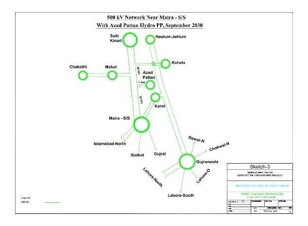
The interconnection scheme of the project to evacuate its maximum power is envisaged to be connected by looping in-out with 500 kV circuit from Kohala HPP to Maira Substation. The looping distance is around 1 km (just to get to the other side of the river), using 500 kV Bunting/high-capacity conductor.
The broad scope of switchgear at the project substation would be based on breaker and half scheme. A total of nine breaker bays (3 Dias) would be connected as:
Load Flow and Short Circuit Analysis
Detailed load flow studies have been carried out for the peak and off-peak load conditions of high-water case of 2024 and for the peak load conditions of low water case of January 2025. Short circuit and stability analyses have been carried out for the system conditions of 2024-25 and for the future scenario of 2030. The short circuit analysis performed on the case of 2024-25 reveals that the short circuit level of the project 500 kV is 28.41 kA and 17.66 kA while the level in year 2030 is 29.79 kA and 17.91 kA for 3-phase and 1-phase faults respectively.
Therefore, the industrial standard rating of 50 kA is adopted for all the switchgear equipment to take care of huge fault current contribution from future generation additions to be connected with the same 500 kV network. These analysis reveals that interconnection scheme is adequate to evacuate the maximum power of 700.7MW of the plant under normal and contingency conditions.
Dynamic Study Analysis
The dynamic stability analysis of the interconnection has been carried out for the peak case of summer 2024. The stability check for the worst case of 3-phase fault right on the 500 kV bus bar of the project substation followed by the final trip of 500 kV circuits emanating from this substation, has been performed for fault clearing of 5 cycles (100 ms) to be the normal fault clearing time of 500 kV protection system as per Grid Code requirement.
The system is found strong enough to stay stable and recovered with fast damping. The scheme successfully passed the dynamic stability checks for the worst cases and has no technical constraints/problems and it fulfils all the criteria of reliability and stability under steady state load flow, contingency load flows, short circuit currents and dynamic/transient conditions.
The following diagram provides the approved transmission scheme for the Project.